METRON / Hunter Transducers
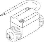
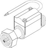
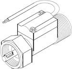
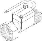
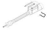
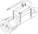
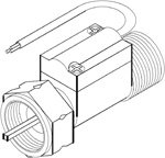
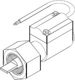
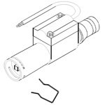
Transducer Type 310
Order Code: 310/…
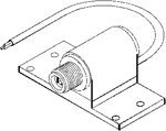
Standard Configuration:
- Single M12 male fitting
- 3.1mm square drive
- Flanged for surface mounting
- 12 volt electronics
- 2 metres of electrical cable
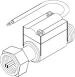
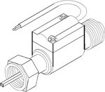
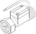
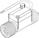
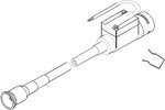
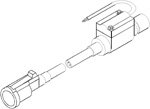
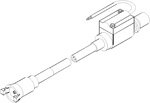
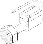
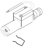
Transducer Type 311
Order Code: 311/…
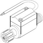
Standard Configuration:
- M12 male and female fittings
- 3.1mm square drive
- 12 volt electronics
- 2 metres of electrical cable
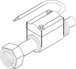
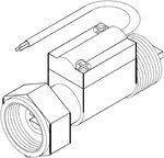
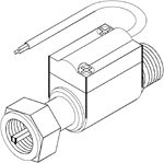
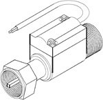
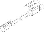
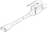
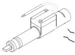
Transducer Type 312
Order Code: 312/…
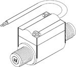
Standard Configuration:
- M12 male fittings
- 3.1mm square drive
- 12 volt electronics
- 2 metres of electrical cable
Notes:
May be used for universal installations, however, we recommend our Type 320. Cable fittings should be ordered separately.
May be used for universal installations, however, we recommend our Type 320. Cable fittings should be ordered separately.
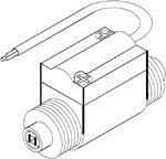
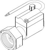
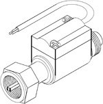
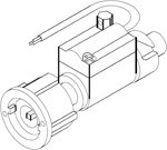
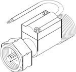
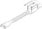
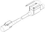
Transducer Type 314
Order Code: 314/…
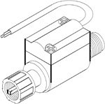
Standard Configuration:
- M12 male and female fittings
- 2.7mm square drive
- 12 volt electronics
- 2 metres of electrical cable
Transducer Type 320
Order Code: 320/…
Standard Configuration:
- M18 male fittings
- 2.7mm square drive
- 12 volt electronics
- 2 metres of electrical cable
Notes:
Standard 12 volt Universal Transducer. Refer to Installation Note 1 for cable kit fitting. Cable fittings should be ordered separately.
Standard 12 volt Universal Transducer. Refer to Installation Note 1 for cable kit fitting. Cable fittings should be ordered separately.
Transducer Type 321
Order Code: 321/…
Standard Configuration:
- M18 male and female fittings
- 2.7mm square drive
- 12 volt electronics
- 2 metres of electrical cable
Transducer Type 322
Order Code: 322/…
Standard Configuration:
- M18 male and female fittings
- 2.7mm square drive
- 12 volt electronics
- 2 metres of electrical cable
Transducer Type 324
Order Code: 324/…
Standard Configuration:
- M18 male fittings
- 2.7mm square drive
- 24 volt electronics
- 2 metres of electrical cable
Notes:
Standard 24 volt Universal Transducer. Refer to Installation Note 1 for cable kit fitting. Cable fittings should be ordered separately.
Standard 24 volt Universal Transducer. Refer to Installation Note 1 for cable kit fitting. Cable fittings should be ordered separately.
Transducer Type 328
Order Code: 328/…
Standard Configuration:
- M18 male and female fittings
- 2.7mm square drive
- 24 volt electronics
- 2 metres of electrical cable
Transducer Type 329
Order Code: 329/…
Standard Configuration:
- M18 male and female fittings
- 2.7mm square drive
- 12 volt electronics
- 2 metres of electrical cable
Notes:
Ford Orion and Mondeo gearbox fittings.
Ford Orion and Mondeo gearbox fittings.
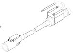
Transducer Type 332
Order Code: 332/…
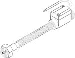
Standard Configuration:
- M18 male and female fittings
- 15cm drive extension
- 2.7mm square drive
- 12 volt electronics
- 2 metres of electrical cable
Notes:
Refer to Installation Note 3 when using these transducers.
Refer to Installation Note 3 when using these transducers.
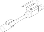
Transducer Type 334
Order Code: 334/…
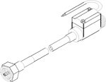
Standard Configuration:
- M18 male and female fittings
- 2.7mm square drive
- 20cm drive extension
- 12 volt electronics
- 2 metres of electrical cable
Notes:
Refer to Installation Note 3 when using these transducers.
Refer to Installation Note 3 when using these transducers.
Transducer Type 340
Order Code: 340/…
Standard Configuration:
- M22 male and female fittings
- Lug drive
- 12 volt electronics
- 2 metres of electrical cable
Notes:
Toyota and Suzuki gearbox fitting. Refer to Installation Note 2 when using these transducers.
Toyota and Suzuki gearbox fitting. Refer to Installation Note 2 when using these transducers.
Transducer Type 341
Order Code: 341/…
Standard Configuration:
- M22 male and female fittings
- Lug drive
- 12 volt electronics
- 2 metres of electrical cable
Notes:
Nissan and Mitsubishi gearbox fitting. Refer to Installation Note 2 when using these transducers.
Nissan and Mitsubishi gearbox fitting. Refer to Installation Note 2 when using these transducers.
Transducer Type 342
Order Code: 342/…
Standard Configuration:
- M22 male and female fittings
- Blade drive
- 12 volt electronics
- 2 metres of electrical cable
Notes:
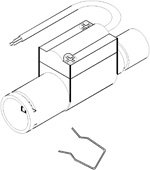
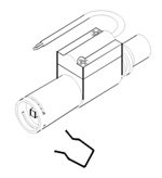
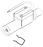
Supplied with anti spreading ring. Refer to Installation Note 4 when using these transducers.
Supplied with anti spreading ring. Refer to Installation Note 4 when using these transducers.
Transducer Type 344
Order Code: 344/…

Standard Configuration:
- M22 male and female fittings
- Blade drive
- Fully sealable
- 12 volt electronics
- 2 metres of electrical cable
Notes:
Supplied with anti spreading ring. Refer to Installation Note 4 when using these transducers.
Supplied with anti spreading ring. Refer to Installation Note 4 when using these transducers.
Transducer Type 345
Order Code: 345/…
Standard Configuration:
- Single M22 female fitting
- Slot drive
- Fully sealable
- 12 volt electronics
- 2 metres of electrical cable
Notes:
Supplied with anti spreading ring. Refer to Installation Note 4 when using these transducers.
Supplied with anti spreading ring. Refer to Installation Note 4 when using these transducers.
Transducer Type 346
Order Code: 346/…
Standard Configuration:
- M22 male and female fittings
- Blade drive
- Fully sealable
- 24 volt electronics
- 2 metres of electrical cable
Notes:
Supplied with anti spreading ring. Refer to Installation Note 4 when using these transducers.
Supplied with anti spreading ring. Refer to Installation Note 4 when using these transducers.
Transducer Type 347
Order Code: 347/…

Standard Configuration:
- Single M22 female fitting
- Slot drive
- Fully sealable
- 24 volt electronics
- 2 metres of electrical cable
Notes:
Supplied with anti spreading ring. Refer to Installation Note 4 when using these transducers.
Supplied with anti spreading ring. Refer to Installation Note 4 when using these transducers.
Transducer Type 350
Order Code: 350/…
Standard Configuration:
- M22 LH and RH male fittings
- Blade drive
- Fully sealable
- 12 volt electronics
- 2 metres of electrical cable
Transducer Type 351
Order Code: 351/…
Standard Configuration:
- 5/8UN male and female fittings
- 2.7mm square drive
- 12 volt electronics
- 2 metres of electrical cable
Transducer Type 353
Order Code: 353/…
Standard Configuration:
- M16 male and female fittings
- 2.7mm square drive
- 12 volt electronics
- 2 metres of electrical cable
Transducer Type 356
Order Code: 356/…
Order Code: 355/… Without cable, same configuration
Order Code: 355/… Without cable, same configuration
Standard Configuration:
- Peugeot gearbox fittings
- 2.7mm square drive
- 15cm drive extension
- 12 volt electronics
- 2 metres of electrical cable
Notes:
Refer to Installation Note 3 when using these transducers.
Refer to Installation Note 3 when using these transducers.
Transducer Type 358
Order Code: 358/…
Standard Configuration:
- Vauxhall speedometer fittings
- 2.7mm square drive
- 20cm drive extension
- 12 volt electronics
- 2 metres of electrical cable
Notes:
Refer to Installation Note 3 when using these transducers.
Refer to Installation Note 3 when using these transducers.
Transducer Type 361
Order Code: 361/…
Standard Configuration:
- 3/4″WHIT male and female fittings
- 3.1mm square drive
- 12 volt electronics
- 2 metres of electrical cable
Transducer Type 363
Order Code: 363/…
Standard Configuration:
- Mechanical tachograph fittings
- 2.7mm square drive
- Fully sealable
- 24 volt electronics
- 2 metres of electrical cable
Transducer Type 364
Order Code: 364/…
Standard Configuration:
- Mechanical tachograph fittings
- 2.7mm square drive
- Fully sealable
- 12 volt electronics
- 2 metres of electrical cable
Transducer Type 365
Order Code: 365/…

Standard Configuration:
- Small twist fittings
- 2.7mm square drive
- 12 volt electronics
- 2 metres of electrical cable
Notes:
Early Volvo speedometer fitting.
Early Volvo speedometer fitting.
Transducer Type 366
Order Code: 366/…
Standard Configuration:
- Snapfit speedometer fittings (Japanese style)
- 2.7mm square drive
- 20cm drive extension
- 12 volt electronics
- 2 metres of electrical cable
Notes:
Refer to Installation Note 3 when using these transducers.
Refer to Installation Note 3 when using these transducers.
Transducer Type 368
Order Code: 368/…
Standard Configuration:
- Snapfit speedometer fittings (Japanese style)
- 2.7mm square drive
- 10cm drive extension
- 12 volt electronics
- 2 metres of electrical cable
Notes:
Refer to Installation Note 3 when using these transducers.
Refer to Installation Note 3 when using these transducers.
Transducer Type 369
Order Code: 369/…
Standard Configuration:
- 7/8UN male and female fittings
- Lug drive
- 12 volt electronics
- 2 metres of electrical cable
Transducer Type 371
Order Code: 371/…
Standard Configuration:
- 7/8UN male and female fittings
- 2.7mm square drive
- 12 volt electronics
- 2 metres of electrical cable
Transducer Type 372
Order Code: 372/…

Standard Configuration:
- Eurosnap speedometer fittings
- 2.7mm square drive
- 15cm drive extension
- 12 volt electronics
- 2 metres of electrical cable
Notes:
Refer to Installation Note 3 when using these transducers.
Refer to Installation Note 3 when using these transducers.
Transducer Type 373
Order Code: 373/…
Standard Configuration:
- Eurosnap speedometer fittings
- 3.1mm square drive
- 45cm drive extension
- 12 volt electronics
- 2 metres of electrical cable
Notes:
Refer to Installation Note 3 when using these transducers.
Refer to Installation Note 3 when using these transducers.
Transducer Type 374
Order Code: 374/…
Standard Configuration:
- Eurosnap speedometer fittings
- 3.1mm square drive
- 30cm drive extension
- 12 volt electronics
- 2 metres of electrical cable
Notes:
Refer to Installation Note 3 when using these transducers.
Refer to Installation Note 3 when using these transducers.
Transducer Type 375
Order Code: 375/…
Standard Configuration:
- Eurosnap speedometer fittings
- 3.1mm square drive
- 15cm drive extension
- 12 volt electronics
- 2 metres of electrical cable
Notes:
Refer to Installation Note 3 when using these transducers.
Refer to Installation Note 3 when using these transducers.
Transducer Type 377
Order Code: 377/…
Standard Configuration:
- Eurosnap speedometer fittings (Ford style)
- 2.7mm square drive
- 15cm drive extension
- 12 volt electronics
- 2 metres of electrical cable
Notes:
Refer to Installation Note 3 when using these transducers.
Refer to Installation Note 3 when using these transducers.
Transducer Type 381
Order Code: 381/…
Standard Configuration:
- Snapfit speedometer fittings (Japanese style)
- 2.7mm square drive
- 12 volt electronics
- 2 metres of electrical cable
Transducer Type 382
Order Code: 382/…
Standard Configuration:
- Eurosnap speedometer fittings
- 2.7mm square drive
- 12 volt electronics
- 2 metres of electrical cable
Transducer Type 383
Order Code: 383/…

Standard Configuration:
- Triggersnap speedometer fittings (Ford style)
- 2.7mm square drive
- 12 volt electronics
- 2 metres of electrical cable
Transducer Type 384
Order Code: 384/…
Standard Configuration:
- Eurosnap speedometer fittings
- 3.1mm square drive
- 12 volt electronics
- 2 metres of electrical cable
Transducer Type 387
Order Code: 387/…
Standard Configuration:
- FX gearbox fitting
- Blade drive
- 12 volt electronics
- 2 metres of electrical cable
Transducer Type 388
Order Code: 388/…
Standard Configuration:
- Metrocab fitting
- Slot drive
- 12 volt electronics
- 2 metres of electrical cable
Transducer Type 390
Order Code: 390/…
Standard Configuration:
- VW speedometer fittings
- 2.7mm square drive
- 25cm drive extension
- 12 volt electronics
- 2 metres of electrical cable
Notes:
Refer to Installation Note 3 when using these transducers.
Refer to Installation Note 3 when using these transducers.
Transducer Type 391
Order Code: 391/…
Standard Configuration:
- VW speedometer fittings
- 2.7mm square drive
- 10cm drive extension
- 12 volt electronics
- 2 metres of electrical cable
Notes:
Refer to Installation Note 3 when using these transducers.
Refer to Installation Note 3 when using these transducers.
Transducer Type 394
Order Code: 394/…
Standard Configuration:
- C25 speedometer fittings
- 2.7mm square drive
- 12 volt electronics
- 2 metres of electrical cable
Transducer Type 395
Order Code: 395/…
Standard Configuration:
- C25 speedometer fittings
- 3.1mm square drive
- 12 volt electronics
- 2 metres of electrical cable
Transducer Type 396
Order Code: 396/…
Standard Configuration:
- C25 gearbox fittings
- Blade drive
- 12 volt electronics
- 2 metres of electrical cable
Transducer Type 397
Order Code: 397/…
Standard Configuration:
- VW speedometer fittings
- 2.7mm square drive
- 22cm drive extension
- 12 volt electronics
- 2 metres of electrical cable
Notes:
Refer to Installation Note 3 when using these transducers.
Refer to Installation Note 3 when using these transducers.